Highlight:
dense phase pneumatic conveying pump
, high efficiency silo pump
, material transfer bin pump
Name: |
Pneumatic Conveying Silo Pump |
Model: |
PCD |
Tank Structure: |
Vertical Cylinder |
Pump Inner Diameter: |
800mm, 1200mm, 1400mm, 2400mm |
Performance: |
Dense Phase Positive Pressure Conveying |
Applications: |
Power Plant Fly Ash, Cement, Raw Materials, Mineral Powder, Etc |
Main Material: |
Q235 Carbon Steel, 304 Stainless Steel, 316 Stainless Steel |
Application: |
Power Plant Fly Ash, Metallurgy, Mining, Chemical Industry, Etc |
Purpose: |
Transporting Powdered Materials |
Valve Configuration: |
The Feed Valve Uses A Conical Valve, And The Discharge Valve Uses A Wear-resistant Ball Valve Or Dome Valve, Including An Exhaust Valve/pressure Relief Valve |
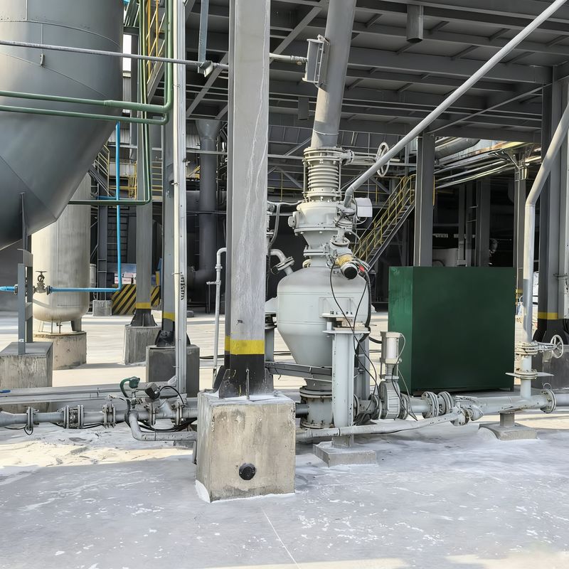
Dense Phase Pneumatic Conveying Bin Pump | Silo Pump – High Efficiency Material Transfer
Structural Composition
Main Vessel: Typically configured as a vertical cylinder, with some horizontal designs. Material selection depends on product characteristics, commonly using Q235 carbon steel or 304/316 stainless steel. Large vessels are often divided into upper and lower chambers separated by a flow guide cone or distribution plate. The design pressure generally ranges from 0.2 to 1.0 MPa, with pressure measurement ports and safety valve interfaces reserved on the top or side.

Large Capacity Pneumatic Conveying Bin Pump Parameter Table
| Conveying Material |
Bulk Density (t/m³) |
Model |
PCD24/H |
PCD26/H |
PCD28/H |
PCD30/H |
Conveying Distance |
| Specification |
16~20m3 |
18~22m3 |
20~27m3 |
26~32m3 |
Level (m) |
Level (m) |
| Pulverized Coal |
0.5 |
Delivery Volume (t/h) |
50~80 |
60~90 |
65~110 |
80~130 |
200 |
20 |
| Fly Ash |
0.75 |
75~125 |
85~130 |
95~160 |
125~190 |
200 |
20 |
| Limestone Powder/Mineral Powder |
0.8 |
80~130 |
90~140 |
100~170 |
130~200 |
200 |
20 |
| Cement/Raw Meal |
1 |
100~150 |
115~175 |
130~215 |
165~260 |
200 |
20 |
Long-distance Pneumatic Conveying Bin Pump Parameter Table
| Conveying Material |
Bulk Density (t/m3) |
Model |
PCD24/L |
PCD26/L |
PCD28/L |
PCD30/L |
Conveying Distance |
| Specification |
16~20m3 |
18~22m3 |
20~27m3 |
26~32m3 |
Level (m) |
Level (m) |
| Pulverized Coal |
0.5 |
Delivery Volume (t/h) |
20~40 |
25~45 |
30~55 |
45~65 |
1000 |
25 |
| Fly Ash |
0.75 |
35~60 |
45~65 |
45~80 |
65~95 |
1000 |
25 |
| Limestone Powder/Mineral Powder |
0.8 |
40~65 |
45~70 |
50~85 |
70~100 |
1000 |
25 |
| Cement/Raw Meal |
1 |
50~80 |
55~90 |
65~110 |
90~120 |
1000 |
25
|
Conventional Grid Pneumatic Conveying Bin Pump Parameter Table
| Conveying Material |
Bulk Density(t/m³) |
Model |
PCD18/N |
PCD20/N |
PCD20/N |
Reference Conveying Distance |
| Specification |
5.0~6.7m³ |
7.0~10.0m³ |
10.0~15.0m³ |
Level (m) |
Vertical (m) |
| Pulverized Coal |
0.5 |
Delivery Volume (t/h) |
12~20 |
16~32 |
25~50 |
500 |
30 |
| Fly Ash |
0.75 |
18~32 |
25~48 |
35~70 |
50 |
|
| Limestone Powder/Mineral Powder |
0.8 |
20~35 |
26~51 |
38~75 |
500 |
30 |
| Cement/Raw Meal |
1.0 |
24~42 |
32~65 |
48~95 |
500 |
30 |
| Silicon Powder |
1.2 |
28~50 |
40~75 |
55~115 |
500 |
30
|
Parameter Table Of Small Size Pneumatic Conveying Bunker Pump
| Material |
Bulk Density(t/m³) |
Model |
PCD08/M |
PCD10/M |
PCD12/M |
PCD14/M |
Reference Conveying Distance |
| Specification |
0.2~0.5m³ |
0.6~1.6m³ |
1.5~2.5m³ |
2.5~5.0m³ |
Level (m) |
Vertical (m) |
| Pulverized Coal |
0.5 |
Delivery Volume (t/h) |
0.5~1.8 |
1.5~5.5 |
5.0~9.0 |
8.0~18.0 |
100 |
20 |
| Fly Ash |
0.75 |
0.9~2.8 |
2.5~8.5 |
7.0~14.0 |
12.0~27.0 |
100 |
20 |
| Limestone Powder/Mineral Powder |
0.8 |
1.0~3.0 |
3.0~9.0 |
8.0~15.0 |
12.0~28.0 |
100 |
20 |
| Cement/Raw Meal |
1.0 |
1.2~3.5 |
3.5~11.5 |
10.0~18.0 |
16.0~36.0 |
100 |
20 |
| Silicon Powder |
1.2 |
1.5~4.0 |
4.5~13.5 |
12.0~20.0 |
19.0~43.0 |
100 |
20 |
Feed and Discharge System
The feed inlet is typically located at the top of the vessel, connecting to upstream silos or feeders, and commonly employs pneumatic gate valves or wear-resistant butterfly valves as feed valves. The discharge outlet is situated at the bottom or on the side of the lower vessel, connecting to the conveying pipeline, and often uses pneumatic ceramic ball valves or double-gate slide plate valves as discharge valves. Dense phase pressure vessels are equipped with fluidization discs or fluidization pipes at the bottom to facilitate material fluidization.
Pneumatic Control System
This system comprises the compressed air inlet with pressure regulating valves, pneumatic valve groups, pressure detection and control components, and venting/pressure relief devices. Compressed air is supplied from an external compressor and directed through the pneumatic valve group to actuate the opening and closing of the feed, discharge, and vent valves. Pressure sensing elements monitor the vessel pressure in real time, while the vent valve and safety valve work in concert to maintain stable pressure within the vessel.
Auxiliary Equipment
Auxiliary components include level detection devices, blowdown and cleaning mechanisms, and support/frame structures. The vessel is equipped with a level gauge to monitor material height, and a blowdown valve at the bottom allows for the removal of accumulated dust or contaminants. Large pressure vessels are typically fitted with access ladders and platforms to facilitate maintenance.
Working Principle
The conveying process of a pressure vessel (blow tank) operates in a cyclic manner. Initially, all valves are closed. The cycle begins with the opening of the feed and vent valves, allowing the vessel to fill with material at atmospheric pressure. Once the level detector signals that the vessel is full, the feed and vent valves close. The high-pressure air valve then opens to pressurize the vessel.
After reaching the operational pressure, the conveying air valve and discharge valve open, initiating material transport. Upon completion of conveying, the high-pressure air valve and discharge valve close. The conveying line is purged with compressed air, while the vent valve opens to depressurize the vessel back to atmospheric pressure, thus completing one full working cycle.
Main Features
High Energy Efficiency: Optimized fluidization structure ensures excellent material fluidization with low air consumption.
High Material-to-Air Ratio: Superior fluidization efficiency minimizes air usage, achieving material-to-air ratios exceeding 30 kg (material) / kg (air).
Low Material Velocity: Materials move in a dune flow regime within the pipeline, resulting in minimal wear on valves and piping, and extended service life for wear-prone parts.
Strong Regulation Capability
Equipped with multiple adjustment means, including primary and secondary air intake regulation, enabling system operation with an optimal air supply ratio and superior fluidization conditions.
Application Fields
Pressure vessels (blow tanks) for pneumatic conveying are widely used in industries such as metallurgy, building materials, grain processing, and food. They are suitable for powder conveying, environmental dust collection, and granular material transport. These systems enable fully sealed, contamination-free conveying, complying with environmental protection standards.
Why Choose Our System?
Superior Reliability Backed by Innovation
• Patented pressure vessel structure – delivers 20% longer service life than industry counterparts
• Intelligent auto pressure regulation – ensures consistent material flow without pulsation or blockages
Intuitive & Connected Smart Operation
• PLC + touchscreen control panel – pre-storable recipes for quick switching between different materials
• 24/7 remote monitoring – real-time performance tracking and data analysis via mobile app or PC platform
Compliant & Trusted for ASEAN Markets
• CE & ATEX dual certification – fully meets regional safety and environmental standards
• Localized technical support – tailored to ASEAN industrial requirements and regulations

 Your message must be between 20-3,000 characters!